The Hapticlabs satellite is the hardware core of Hapticlabs. It serves to drive haptic actuators which a standard computer could not handle by itself.
Hardware Interface
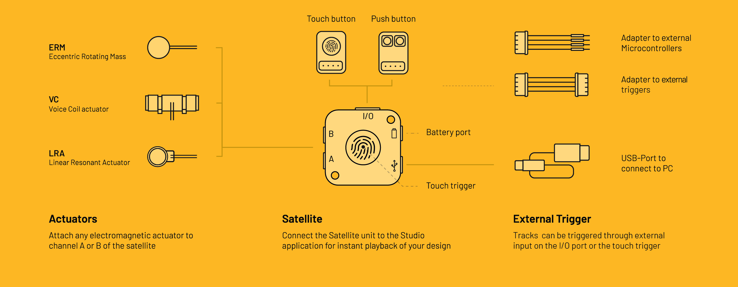
- Two independent channels A and B for connecting actuators
- Universal Port I/O
- Battery Port
- USB-C Port
- Capacitive touch trigger
- Internal storage for up to ~2500 haptic signals
- * Bluetooth Low Energy (BLE) & WIFI-capable (*currently in BETA)
The Hapticlabs Satellite is a hardware module incorporating an Espressif ESP32 MCU and two Texas Instruments DRV2605 haptic drivers. It allows instantly playback of haptic signals designed in Hapticlabs Studio. The communication is established through a UART Serial communication via the USB port.
The module’s internal haptic engine is optimized to play back haptic signals on electromagnetic haptic actuators, including LRAs (Linear Resonant Actuators), ERMs (Eccentric Rotating Masses), and voice coils, accounting for their respective properties.
The Hapticlabs Satellite can store haptic tracks designed in Hapticlabs Studio in its internal storage. This enables playback of these tracks even without communication to Hapticlabs Studio. The playback can be triggered through external sensors connected via the universal Port I/O, the capacitive touch trigger, located in the Center of the Satellite or the UART interface on the hardware module.
The firmware running on the device is regularly and automatically updated through Hapticlabs Studio.
Specifications can be found within the data sheet.
A and B Channel
The satellite features two output channels highlighted in yellow, designated as "A" and "B", where any electromagnetic actuator can be connected. These channels function entirely independently, supporting combinations of various actuator types and simultaneous playback of different haptic signals. Find out more about the Channel Settings in Hapticlabs Studio in the Setellite Output section.
Universal port I/O
The Hapticlabs Satellite features a universal port. Its position is indicated by an “I/O” label on the casing. It consists of a ground connection (labeled GND), a 3.3 V power connection (labeled 3.3V), and two multi-purpose contacts (labeled PIN1 and PIN2). The labels are printed on the underside of the Printed Circuit Board (PCB). The Universal Port can be utilized to connect sensors such as the Touch & Push Button, which are included in the DevKit. Further Informations can be found in the Sensor Input section.
Battery port
Next to the USB-C port, labeled with a battery symbol, there is a battery port. Here, you can connect a 3,7V LiPo Battery to power the satellite. Further Informations can be found in the Power Management section.
USB-C port
The USB symbol on the casing indicates the position of the female USB-C port. The Hapticlabs Satellite will communicate through this port to your computer and Hapticlabs Studio. Connect a USB cable to this port and to a USB-A or a USB-C port of your computer. A yellow LED on the Hapticlabs Satellite will light up once the Satellite receives power. Further Informations about connecting the Satellite to Hapticlabs Studio can be found in the Satellite output section.
Touch trigger
On the top side of the Hapticlabs Satellite, in the center of the Hapticlabs logo, there is a capacitive touch sensor. You can visually locate it as a small metal area. Touch this sensor to trigger the track that has been saved to Pin 1 in the external trigger menu in Hapticlabs Studio.
Casing

The Hapticlabs Satellite comes with a semi-clear plastic casing. It is possible to remove this casing to expose the Printed Circuit Board (PCB). Use a flathead screwdriver to enter the opening on the side of the satellite to unlock the case parts. Only use minimal force to prevent damaging the case.